Diffuser Cad Block Free Plugin Tutorial Video
What is a Diffuser in HVAC System?
A Diffuser is a device designed to distribute airflow, usually installed at the end of the ductwork. Its primary functions are to reduce air velocity and mixing air in the room.
The diffuser blades are angled to optimize air distribution patterns. It is often used for supply air applications rather than return air applications.
⚙️ Diffuser Classification Guide
Classification by shape (concentric blade design): Based on the concentric blade configuration, diffusers are categorized into 2 types:
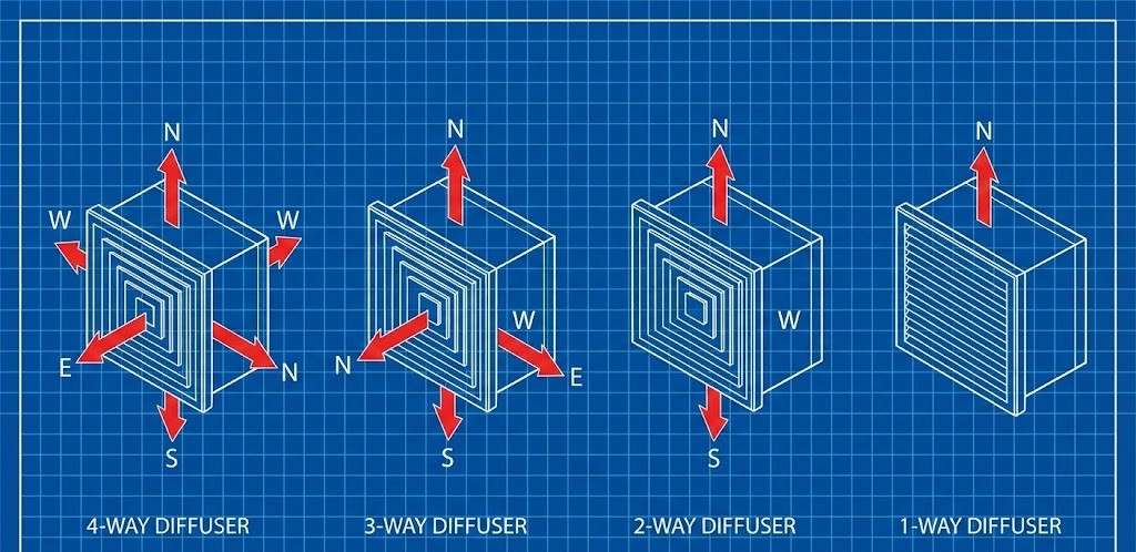
Classification by airflow distribution direction (throw pattern): In terms of airflow direction and distribution patterns, diffusers are classified into 4 types:
HVAC Diffuser Calculator
Diffuser Sizing Calculator
Diffuser Cheat Sheet HVAC
Square Diffuser Sizing Chart
Reference based on Neck Velocity (2.5 – 4.0 m/s)
| Neck Size (mm) | Size (Inch) | Range (CFM) | Range (CMH) |
|---|---|---|---|
| 150 x 150 | 6″ x 6″ | 60 – 160 | 100 – 270 |
| 200 x 200 | 8″ x 8″ | 150 – 290 | 250 – 500 |
| 250 x 250 | 10″ x 10″ | 250 – 470 | 420 – 800 |
| 300 x 300 | 12″ x 12″ | 350 – 650 | 600 – 1100 |
| 350 x 350 | 14″ x 14″ | 500 – 900 | 850 – 1500 |
| 400 x 400 | 16″ x 16″ | 700 – 1200 | 1200 – 2000 |
| 450 x 450 | 18″ x 18″ | 900 – 1500 | 1500 – 2500 |
| 500 x 500 | 20″ x 20″ | 1100 – 1900 | 1900 – 3200 |
| 600 x 600 | 24″ x 24″ | 1600 – 2800 | 2700 – 4800 |
Understanding Diffuser Functions
📍 Diffuser Strategy: Positioning & Quality
Understanding diffuser functions will help us design a comfortable and efficient air conditioning system. A diffuser is not just an ordinary accessory used to cover a ducting hole. It is a key component that determines how cold air is distributed throughout a room. If the placement and sizing are incorrect, occupants might feel the airflow is too strong and cold on their heads, or conversely, some corners of the room might remain hot because the air simply does not reach them.
In the process of creating a diffuser AutoCAD drawing, a drafter must consider both aesthetic and technical aspects simultaneously. Why must aesthetics be considered for a diffuser? Because the diffuser’s face is always visible.
Essentially, its face or fascia is what the user or owner will see every day on the ceiling or walls. Diffusers are typically installed on the ceiling, so their positions must align with the ceiling grid pattern, lighting fixtures, fire sensors, and other interior devices. Using our free diffuser CAD block plugin will help us quickly determine precise coordinate points without having to manually redraw every line each time there is a change in the neck or face size.
Beyond air distribution or throw, another parameter frequently monitored by engineers is the noise criteria (NC) or noise level. A diffuser that is too small for a large air capacity will produce a whistling noise that disrupts comfort.
This is why synchronizing the calculator results with the diffuser AutoCAD drawing in the shop drawing is critical. Consistent symbols and measurements in the drawing will make it easier for the field team during installation and ensure the HVAC system is built with a high quality standard.
Example Case of Calculating Diffuser
📝 Example Case: Determining Diffuser Size
First, convert mm to meters (250 mm = 0.25 m):
Use the formula V = Q / A. Since the airflow (Q) is in CMH, we divide by 3600 to convert hours to seconds:
Velocity = 0.1388 ÷ 0.0625
Velocity = 2.22 m/s
Based on HVAC comfort standards, the target Optimal Velocity is 2.0 – 4.0 m/s.
Since our calculation result is 2.22 m/s, the status is: OPTIMAL.
Conclusion: The 250 x 250 mm diffuser size is perfectly suitable for a 500 CMH requirement. The air will be distributed evenly without producing whistling noises that could disrupt the meeting.